


DIY Radio Broadcasting Station
Objective
This manual can be used to inexpensively build classic analog radio frequency circuits - electronics that generate "waves of electricity" in free air or "free space".
More importantly, this project will help demystify important misnomers about complexity or mysteriousness about wireless communication. Radio waves are health-wise safest due to their low frequency. They are between 3 kHz (3 * 10^3 Hz) to 300 Ghz (3 * 10^6 Hz) and are used in commercial radio in car's, or MRI imaging in medicine, Intra-network communications as seen in Cordless Phones, Walkie Talkies and many other communication technologies.
Most freshmen engineering students will learn from this hands-on DIY about:
Examples of Signals and Systems
Differences between radiations in the electromagnetic spectrum
Tranducer
Oscilliator of DC signals
Modulator
Signalling Theory
Transmission of Information Wirelessly
This project is one in several that will lead to stronger applied foundations in radio technology. Expertise in this realm of electricla engineering will help the student to understand other "wireless technologies" in consecutive and more challenging projects in the areas of SONAR and RADAR and Radio Frequency and Microwave Engineering. This discipline's relevance to modern life is indispensible, given our century the century of information delivered wirelessly.
Description
The radio signal strength is ideal for transmission with radius of 1 meter in 3D coordinates. The range of radio signals emitted will be very low. This design helps reduce complaints or objections from certain school districts or parents on high energy wireless energy. This project's wireless energy will be 1/1 000 000 th of a cell phone broadcast tower. The energy is in 50mVolts for Amplitude modulated signals at fixed frequency of 1100 kHz
This project uses circuit elements of resistors, capacitors, inductors to make a hardwired radio broadcasting station. The functoinal blocks of the radio broadcaster or transmitter is illustrated in Figure 1
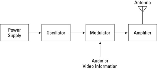
Figure 1 (a) DC current from battery is oscillated into a carrier frequency, which is then modulated according to the amplitudes of the input speech signal.
Figure 1 (b) Oscillitating waves will induce tiny AC current in an antenna. These waves will be very low voltage proportional to the modulated amplitude of the transmitter and have identical frequencies.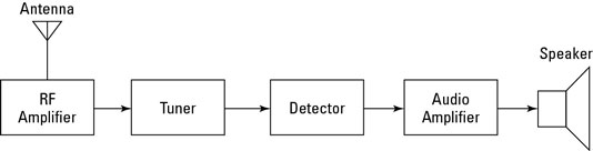
Resources
The student must check through all of the following materials. Missing components can be ordered from the websites, i.e. dx.com, fasttech.com, canada.newark.com, ebay.com, sparkfun.com, adafruit.com, and other website that gives you an inexpensive deal on your component/parts list. The students needs:1 microphone speaker
2 transformers
1 3.3 uF capacitor
1 0.1 uF capacitor
1 variable capacitor
1 470 ohm resistor
1 47k ohm resistor.
1 PNP transistor
1 wire antenna.
1 breadboard
A radio receiver, comes wuth...
Oscilliscope
Breadboard (not bread! It has many perforations) Please see Figure 2.
- Jumper Wires
Method
Step 1 Make the Circuit (Radio Transmitter) from Schematic
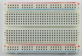
Figure 2 A bread board allows you to rapidly prototype real circuits from schematics.
Step 2 Get Data from Transmitter
Set your radio receiver to 1100kHz. As you will turn the knob on the variable capacitance, you will effectively increase the capacitance. Capacitors cause the current to flip-flop: change directions. Oscilliator cictuit within the schematic makes direction of Direct Current change super fast, at every 1 millions of a second or more. This converts to a carrier frequency of x Hz.x Hz is a determined by the capacitance of the tuning circuit in the schematic: the variable capacitor
Write down what frequencies of oscilliation you get as you decrease variable capacitor to it's least value, and then increase it to it's maximum. Use an USB oscilliscope to visualize these waveforms.
Step 3 Broadcast Your Music/Speech !
Now listen to yiur radio receiver. Place it arond a radius of 1/2 meter around the antenna. Talk or put music nera the speaker. Liten and enjoy.
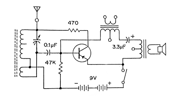
FIGURE 3 The circuit schematic consisting of oscilliator, transducer, transmitter enabling radio functionalities.
Imperative Areas in Need of Improvement
This consecutive lab could have a GUI interface that allows students to select the frequency of the oscillitaor through the computer. The GUI should also show in a window the graph of the data.
Range of 1 meters of wirless communication must be increased to atleast 500 meters. Adding an operation amplifier to amplify the voltage signal of the modulated carrier frequency will achieve this.
Further Readings
To have a deepened knowledge in Radio Frequency Engineeringyou should first gain a "knowledge scaffold and learning directions" of powerful math, science, computer technologies and engineering. Learn more as a student or teacher from free schools:
Once you are confident, please Search with keywords "Radio Electronics Cookbook", "RF Engineering", "Wireless Communication" at UOIT Library or Open Textbooks and Open Encyclopediae:

This work is licensed under a Creative Commons Attribution-NonCommercial-NoDerivs 3.0 Unported License.